The 8×8 LED matrix is 64 LEDs arranged in an 8 row, 8 column matrix, just like a chess board.
The Max7219 is used to control 64 LEDs at once. The Arduino sends data to the 7219 using the SPI serial communication protocol. You can have multiple SPI devices connected to an Arduino simultaneously.
For your convenience, the Arduino uses a library to talk to the LED driver. The library takes care of the SPI communication and may also have methods for writing characters or scrolling images. There are a number of Arduino libraries for MAX7219. I happened to chose LedControl.
Download the latest version of LedControl here (I used v1.0.1): https://github.com/wayoda/LedControl/releases
In-depth about the LedControl library, and a bit about the hardware. You don’t have to read it to follow the instructions in this article, but I scavenged a lot of info here: http://playground.arduino.cc/Main/LedControl
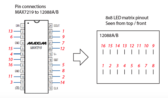
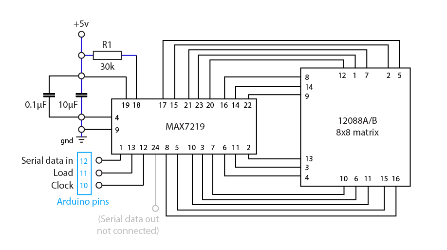
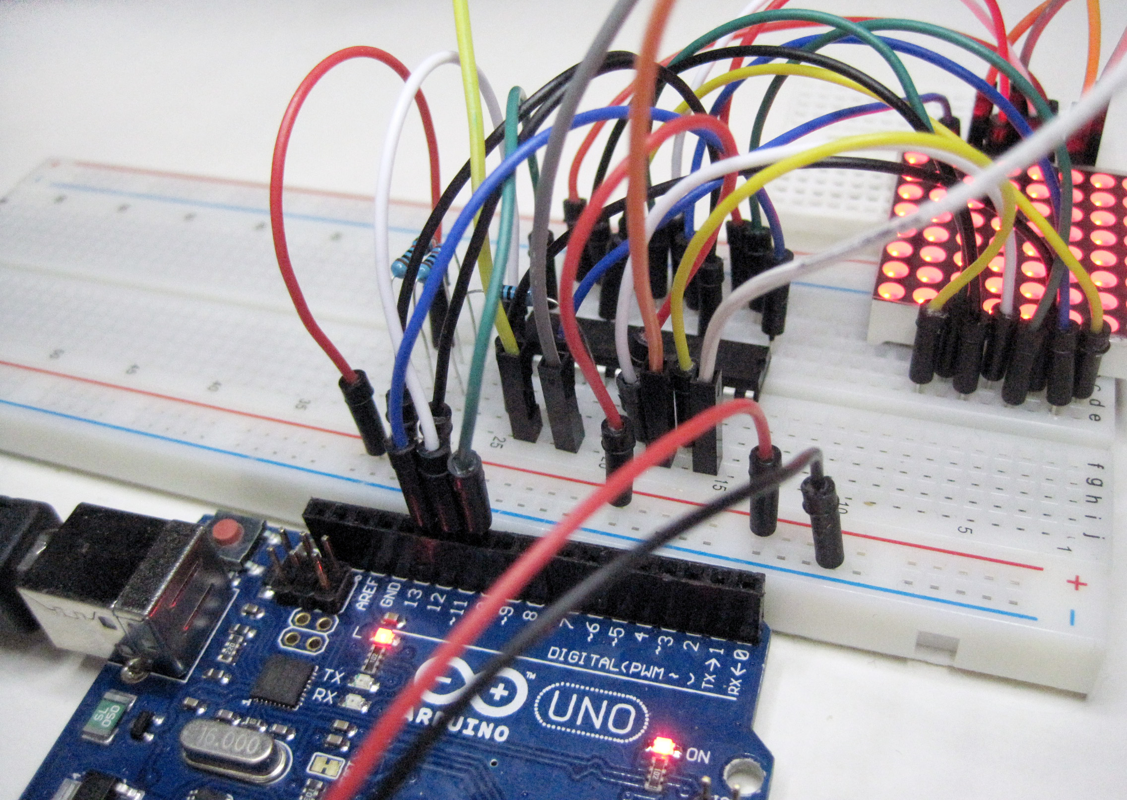
The hard part is to figure out the pin configuration of the 12088A/B LED matrix, and how to connect it to the 7219. So here are some images to help you out.

#include "LedControl.h"

/****
   pin 12 is connected to the MAX7219 pin 1
   pin 11 is connected to the CLK pin 13
   pin 10 is connected to LOAD pin 12
   1 as we are only using 1 MAX7219
*/

LedControl lc = LedControl(12,11,10,1);

void setup() {
  // The zero is the MAX7219 id number, use 0 if there's only one chip
  lc.shutdown(0, false);  // Turn off power saving, enable display
  lc.setIntensity(0, 10); // Set brightness (0~15)
  lc.clearDisplay(0);     // Clear screen

  //lc.setLed(0,1,1,true); // turns on LED at col, row
  Serial.begin(9600);
  pinMode(2, INPUT);
}


void loop() {
  for (int row=0; row<8; row++) {
    for (int col=0; col<8; col++) {
      lc.setLed(0,col,row,true); // turns on LED at col, row
      delay(5);
    }
  }

  for (int row=0; row<8; row++) {
    for (int col=0; col<8; col++) {
      lc.setLed(0,col,row,false); // turns off LED at col, row
      delay(5);
    }
  }
}

