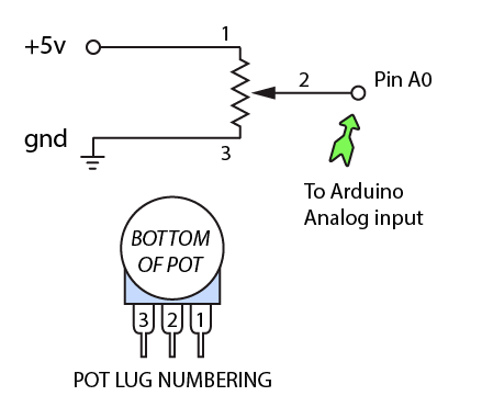
The pot controls which LED is turned on. The pot is connected to Arduino pin A0. analogRead is used to measure the voltage at A0.
You will get a value between 0 and 1023 (where 0 equals ground and 1023 equals +5 volts). The analog range is divided into 5 sections (1023 / 5).
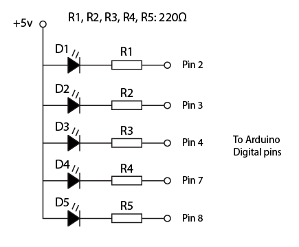
Five LEDs are connected to the digital pins 2, 3, 4, 7 and 8. Use a switch statement to address individual pins depending on pot rotation.
Use a small delay to let the circuitry rest before doing the subsequent read, or the value can be erroneous.
Code
void setup() {
  Serial.begin(9600); // Set up serial communication with the computer
  pinMode(2, OUTPUT);
  pinMode(3, OUTPUT);
  pinMode(4, OUTPUT);
  pinMode(7, OUTPUT);
  pinMode(8, OUTPUT);
}

void loop() {
  int analogValue = analogRead(A0);  // Read the input on analog pin 0
  int pinSelect = analogValue / 204;
  Serial.println(pinSelect);         // Print value to serial monitor
  delay(1);                          // Don't do analogRead too often

  digitalWrite(2, HIGH);
  digitalWrite(3, HIGH);
  digitalWrite(4, HIGH);
  digitalWrite(7, HIGH);
  digitalWrite(8, HIGH);

  switch(pinSelect) {
    case 0:
      digitalWrite(2, LOW);
      break;
    case 1:
      digitalWrite(3, LOW);
      break;
    case 2:
      digitalWrite(4, LOW);
      break;
    case 3:
      digitalWrite(7, LOW);
      break;
    case 4:
      digitalWrite(8, LOW);
      break;

  }
}